Thursday

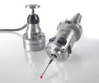
3-D Touch Probes for 3rd Party Controls

its 3-D touch trigger probes to make them available to be used on many CNC controls for milling, drilling and boring machines, and machining centers.
The company said its UTI 192 Universal Touch Probe Interface makes its probes compatible with CNC controls via a fast switching input.
The UTI 192 supports two lines Heidenhain 3-D touch probes, the TT tool touch probes and TS workpiece touch probes. This interface is designed to convert output signals of the Heidenhain 3-D touch probe to the machine control signals in accordance with IEC 61 131-2
Heidenhain said the probing functions that are actually available on the machine depend on the software cycles that are implemented in the respective control. The company offers cycles for automatic alignment and measurement of workpieces, workpiece presetting, and tool measurement on non-TNC controls.
The UTI 192 features a compact design, and can be fastened quickly on a standard mounting rail in the electrical cabinet. Heidenhain said it features a wide range of interfacing possibilities so that the touch probes can easily be connected to the different controls.

waterjet cutting


Process Description
The waterjet cutting process uses a low volume, very thin stream of ultra high pressure water for cutting high precision parts. This thin stream of water leaves the cutting head at over twice the speed of sound, which is why it is able to cut such a wide variety of materials. The application of the waterjet cutting process can be further categorized into two separate processes - abrasive and non-abrasive cutting.


Waterjet Cutting (Non-Abrasive)
The waterjet cutting process begins with an ultra high pressure pump that can deliver water at pressures up to 60,000 PSI through a plumbing system to a cutting head. Inside the cutting head, a sapphire, ruby, or diamond orifice restricts the high pressure water flow to a diameter ranging from 0.002" to 0.025". This focused stream of supersonic water is capable of cutting rubber, plastics, food, insulation, cardboard, carpeting, and many other soft materials. As most of these materials are so easily cut, a large number of water jet systems purchased for cutting soft materials are configured with two or more cutting heads, thereby greatly increasing the production capability of the machine.


Waterjet Cutting (Abrasive)
Harder materials can be cut when an abrasive powder, such as garnet, is mixed in with the stream of water. The abrasive cutting head incorporates a mixing chamber below the orifice. The flow of high pressure water through this chamber creates a venturi effect, which in turn draws abrasive powder into the stream. This abrasive enriched waterjet stream is then re-focused by a mixing tube, which typically has an internal diameter between 0.020" to 0.050". The exiting abrasive stream produces a kerf width that is roughly the same size as the nozzle ID and is ideal for cutting aluminum, steel, titanium, granite, marble, composites, wood, glass and many other materials.

HEIDENHAIN Now Offers One of the Most Accurate 3-D Machine Tool Touch Probes in the Market Today

With the introduction of the TS 740 infrared touch probe, HEIDENHAIN offers machine tool users the opportunity to perform measuring tasks that require an especially high probing accuracy and repeatability. Boasting a probing accuracy of ≤ ± 1 µm and a repeatability factor of 2 s ≤ 0.25 µm, the TS 740 workpiece touch probe is one of the most accurate 3D touch probes for machine tools in the market today.
To do this, the HEIDENHAIN TS 740 touch probe features a new sensor whose principle of function is completely different from that of the optical sensor of their standard touch probes. The new technology involves the use of three sensor elements. When probing a workpiece, the stylus is deflected so that a force acts on these elements. This results in the generation of charges that are detected by the electronics and converted into trigger signals. This system allows for more accurate results.
Also in spite of its low probing forces, the TS 740 is designed in such a way that it is well suited for use in modern machine tools with a fast tool changer. Rapid acceleration or deceleration does not cause uncontrolled trigger signals, as is common with those with low probing forces that are typically sensitive to mechanical disturbances.

Sunday

Liquid Tite Conduit

The conduit used here is called "Liquid Tite" I believe. Makes for a clean installation!

A Tribute to John Bogstandard


I've put together a bit of a tribute to the model steam turbine work of Bogstandard, who has contributed a number of articles on the HMEM boards. John is another of those rare guys who not only does fabulous work, but shares his methods in a way that makes it possible for all to learn. One of the most fascinating areas John worked in was that of model steam turbines. I'm quite sure I hadn't seen such a thing before coming across Bog's engines, but they sure look fun:

Faceplates for Eccentric Turning

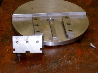
Over the years, some people have built special fixtures to make eccentric turning easier. It's common when building engines and other projects to have to do eccentric turning to create cams or crankshaft offsets. Here is one such faceplate that accomodates either a flat tooling surface or a v-block to hold the workpiece at various offsets


Getting Geared Up to Wire the Box

I've been getting in a plethora of odds and ends to start wiring up the enclosure. I've now got everything except a relay I will use for the E-stop circuit and the master AC on/off switch for the front panel. I also did a number of versions of the overall schematic. The latest is on the enclosure page. Based on my latest schematics, I've done a layout for how I'll go about mounting the various sub-boards in the enclosure:
My goal this weekend would be to get the enclosure to the point I can actually mount the boards and begin the wiring process next weekend, and hopefully try spinning some servos (though not on the machine) next weekend as well. There's quite a bit of work to do there, but if I get enough hours I should reach that stage. Fingers crossed!
I still need to make an arm to support the keyboard and monitor, I need to mount the enclosure to the rolling cabinet, and I also need to paint it.
There's still a lot of fussing. I haven't spec'd or ordered any of the auxilliary panel connectors, for example. I have some sitting around the parts bin that will hopefully work. Have to look at them as well. If need be, I can delay VFD and coolant wiring until after the servos are running and it would be no big deal.

Thursday

CNC Software integrates wtih CATIA V5.

Irvine (CA) - Today CGTech announced the release of VERICUT 5.3, which features a tight integration with CATIA V5.

VERICUT is CNC machine simulation, verification and optimization software that enables users to eliminate the process of manually proving-out NC programs. It reduces scrap loss and rework. The program also optimizes NC programs in order to produce the most efficient tool paths possible that both save time and produce higher quality surface finish. VERICUT supports G-codes or native CAM output to simulate milling, drilling, turning, wire EDM, and mill/turn machining operations.

The CATIA V5-to-VERICUT Interface follows the successful VERICUT interface for CATIA V4, and provides a smooth upgrade path for CATIA users who have transitioned to CATIA V5.

"This is a significant enhancement for VERICUT software and the CATIA community," said Bill Hasenjaeger, Product Marketing Manager at CGTech. "The CATIA V5-to-VERICUT Interface tightly integrates the two programs to help users create the most accurate and efficient NC programs possible. It makes verifying and optimizing NC programs and simulating CNC machines a much easier and more efficient process."

Users can verify individual operations, a series of operations, or a set of complete NC programs. All stock, fixture, and design geometry is automatically transferred to VERICUT in the correct orientation, along with NC program, tooling, machine and control data and other simulation parameters.

VERICUT runs independently of the CATIA process, so you can continue working in CATIA version 5 while simulating and optimizing your NC programs. With VERICUT as your simulation package, you can also verify and optimize NC programs from other CAM systems in CL or post-processed G-code format.

VERICUT runs under Windows and UNIX. CGTech is the recognized world leader in CNC simulation, verification and optimization software technology for manufacturing. The California-based company has subsidiaries in the UK, Germany, France, and Japan, and resellers throughout the world.

GREENING OF THE COMPANY....

Mastercam has made environmental efforts since its inception, before greening became a catch phrase. Efforts made by the company include:

  • Reducing the size of printed product brochures
  • Posting more content to the web site rather than printing on paper
  • Changing the product packaging from four-color printed boxes with coatings to a smaller box using recycled, unprinted cardboard
  • Printing manuals on 100% post-consumer recycled paper

A new 12,000 sq. ft. addition features a soon-to-be-completed 72kw photovoltaic solar array to produce 25% of the company's electricity.

Other efforts include:

  • Geothermal heating and cooling
  • Radiant floor heating
  • Spray foam insulation
  • Insulation under the concrete slab
  • Energy efficient Andersen windows
  • FSC certified lumber – Forestry Stewardship Council
  • Enviro interior doors – no formaldehyde
  • Energy efficient T8 lighting
  • Dual flush toilets and low water use urinals (1 pint)
  • Super engineered thermally efficient NanaWall garage door
  • Solar photovoltaic panels
  • Low-VOC paints and finishes
  • Low-VOC carpet (no PVC)
  • Fresh air exchange
  • Herman Miller modular furniture

MASTERCAM PRODUCT LEVELS

With the release of Mastercam X (10), the application became a true Windows-based application, as opposed to one ported over from DOS. It also represented a fundamental shift in the way the application was configured. Mastercam X2 provided many enhancements over the previous version and adopted a true Windows application feel. Mastercam supports many types of machines, each with a choice of levels of functionality, as well as offers optional add-ins for solid modeling, 4-axis machining, and 5-axis machining. The following list describes the Mastercam product levels:

  • Design—3D wireframe geometry creation, dimensioning, importing and exporting of non-Mastercam CAD files (such as AutoCAD, SolidWorks, Inventor, Parasolid, etc.).
  • Mill Entry—Includes Design, plus various toolpaths (top construction and tool planes only), posting, backplot, verify.
  • Mill, Level 1—Includes Mill Entry, plus surface creation, many additional toolpaths (for all construction and tool planes), highfeed machining, toolpath editor, toolpath transforms, stock definition.
  • Mill, Level 2—Includes Mill, Level 1, plus additional toolpaths, toolpath projection, surface rough and finish machining, surface pocketing, containment boundaries, check surfaces.
  • Mill, Level 3—Includes Mill, Level 2, plus 5-axis wireframe toolpaths, more powerful surface rough and finish machining, multiaxis toolpaths.
  • 5-Axis add-on—5-Axis roughing, finishing, flowline multisurface, contour, depth cuts, drilling, advanced gouge checking.
  • Lathe Entry—3D wireframe geometry creation, dimensioning, importing and exporting of non-Mastercam CAD files (such as AutoCAD, SolidWorks, Inventor, Parasolid, etc.), various toolpaths, backplot, posting.
  • Lathe, Level 1—Includes Lathe Entry, plus surface creation, C-axis toolpaths, stock definition, stock view utility.
  • Router Entry—3D wireframe geometry creation, dimensioning, importing and exporting of non-Mastercam CAD files (such as AutoCAD, SolidWorks, Inventor, Parasolid, etc.), various toolpaths (top construction and tool planes only), toolpath transformation in top plane, backplot, verify, posting.
  • Router—Includes Router Entry, plus surface creation, rectangular geometry nesting, additional toolpaths (for all construction and tool planes), highfeed machining, toolpath editor, full toolpath transformations, stock definition.
  • Router Plus—Includes Router, plus additional toolpaths, toolpath projection, surface rough and finish machining, surface pocketing, containment boundaries, check surfaces.
  • Router Pro—Includes Router Plus, plus True Shape geometry nesting, 5-axis toolpath functionality, multiple surface rough and finish machining, multiaxis toolpaths, toolpath nesting.
  • Wire—2D and 3D geometry creation, dimensioning, various 2-axis and 4-axis wirepaths, customizable power libraries, tabs.
  • Art—Quick 3D design, 2D outlines into 3D shapes, shape blending, conversion of 2D artwork into machinable geometry, plus exclusive fast toolpaths, rough and finish strategies, on-screen part cutting.

CNC SOFWARE/MASTERCAM

Founded in Massachusetts in 1984, CNC Software, Inc. is one of the oldest developers of PC-based CAD/CAM software and one of the first to introduce CAD/CAM software designed for both machinists and engineersMastercam, CNC Software’s main product, started as a 2D CAM system with CAD tools that let machinists create parts on a computer screen, as well as to machine parts in the shop. Since then, Mastercam has grown into the most widely used CAD/CAM package in the world (based on the number of installed seats, as reported by the independent research firm CIMData). CNC Software, Inc. is now located in Tolland, Connecticut.

Mastercam’s comprehensive set of predefined toolpaths—including contour, drill, pocketing, face, peel mill, engraving, surface high speed, advanced multiaxis, and many more—enable machinists to cut parts efficiently and accurately. Mastercam users can create and cut parts using one of many supplied machine and control definitions, or they can use Mastercam’s advanced tools to create their own customized definitions.

Mastercam also offers a level of flexibility that allows the integration of 3rd party applications to address unique machine or process specific scenarios.

Mastercam's name is a double-entendre: it implies mastery of CAM (computer-aided manufacturing), which involves today's latest machine tool control technology; and it simultaneously pays homage to yesterday's machine tool control technology by echoing the older term master cam, which referred to the main cam or model that a tracer followed in order to control the movements of a mechanically automated machine tool.

Sunday

GAUER CNC MACHINE SHOP SERVICES


Gauer Metal Products rates customer satisfaction as important as maintaining the lowest possible price. Delivering the highest quality parts, regardless of complexity, in an inexpensive and timely manner has given Gauer an impeccable reputation over the past 60 years. Whether its a difficult material such as titanium or an extremely complex part, you can count on Gauer to produce results that exceed your expectations.

Quality control is constantly scrutinized by Gauer's experienced professionals who demand only the tightest tolerances. Requiring tight tolerances on everything Gauer produces ensures efficient quality control when it matters most without sacrificing time and in turn cost to the customer.

With over 60 years of experience, Gauer combines old world machining experience with modern CNC/CAM software systems. Modern equipment and tooling alone will not produce quality parts without the knowledge of experienced machinists. This experience gives Gauer a large edge on the competition.


Supplementing Gauer's experience the machine shop is equipped with the latest Mori Seiki CNC machines and the latest in CAM software technology. Our CNC Lathes, Horizontal and Vertical Milling Machines enable Gauer to produce high quality parts at the most competitive prices. Having other capabilities such as welding, burning, punching, and bending, all in house enables Gauer to provide complete fabricating services to fill any requirement. Contact a Gauer sales representative anytime, and receive knowledgeable and courteous support with all of your machining needs.

EDM AND LASER TECHNOLOGY


MC Machinery Systems Inc. is a world leader in EDM and laser technology, exceeding expectations by constantly delivering more sophisticated technology and dependability. Mitsubishi takes a Supply Chain approach to supporting their customers by offering multiple lines of complementary technology, backed by industry-leading customer service and support.

These ever-expanding equipment lines include Roku-Roku High-Speed Vertical Machining Centers for Graphite and Hard Milling of mold components, Small Hole EDM Drills from manual to full CNC versions, Water jet Powered by Mitsubishi Electric in two, four, and five-axis versions, Toyokoki Press Brakes and sheetmetal automation systems to support the laser fabrication industry. 

The Mitsubishi Experience is providing customers with the ingenuity and innovation to stay competitive on all levels. We deliver industry-leading technology and integrated solutions to help you reach new manufacturing heights. The Mitsubishi Experience is the unparalleled support of our sales and service teams, the knowledge of our application engineers, and the expertise from specialists dedicated to maximizing your productivity. Let our experience work for you.

Key Personnel

* Nick Giannotte-Vice President of EDM Sales & Marketing

* Bill Isaac-Vice President of Laser Sales & Marketing

* Lou Clifford-Vice President of Consumable Sales EDM/Laser

* Tony Imbrogno-Vice President of Customer Service & Support

* Pat Simon-Marketing Manager  

CNC PICTURE GALLERY...TURNING CNC M/C

                                               CNC Lathe with Fagor 8070 T CNC System


                                          CNC Lathe with Fagor 8040 TC CNC System


                                               CNC Lathe with Fagor 8040TC CNC System


                                                CNC Lathe with Fagor 8055 TC CNC System


                                                 CNC Lathe with Fagor 8070 T CNC System


                                           CNC Lathe with Fagor 8055 TC CNC System


                                              CNC Lathe with Fagor 8040 TC CNC System


 CNC Lathe with Fagor 8055 TC CNC System


AND MY FRNDS  I WILL PUT MORE PICTURE GALLERY FOR CNC MACHINES.....SOON...WAIT ON THIS BLOG...DO VISIT NEXT TIME..U WILL FIND NEW THING HERE...THANK YOU...JONISH

YES WE CAN....


YES WE CAN....THIS LINE WAS BY BARAK OBAMA AND IT WAS REALLY MOTIVATED...

Saturday

THE VISION THING

Looking ahead, Mr. Burg and others predict that robotic vision technology promises to be the next emerging frontier in automaton. Instead of having a fixture that holds a part to be machined in a specific orientation so the robot knows where to pick it up, today’s automation cells include vision cameras to guide robots. Now operators can simply set a part on a conveyor with an accuracy of plus or minus an inch, and the robotic arm will seek, acquire and grip the part for loading.

Make no mistake; robotic vision technology existed in the mid-1980s. However, only recently have costs fallen to the point that including a camera and the associated software in a system is cost-effective. Vision capabilities that formerly cost in excess of $100,000 for hardware alone can now be brought online for a total cost of about $12,000. Furthermore, software advances have simplified system operations to the point that no special knowledge of programming or engineering is essential to successful operations.

As the metalworking industry becomes increasingly more competitive, more owner/operators are looking to robotics and automation for solutions to the pressures they face to remain productive and profitable. With the proliferation of manufacturers specializing in motion control, workhandling, tooling and software applications for CNC machine tool automation, there has probably never been a more advantageous time for medium- to small-size shops to evaluate a move to automation.

“Today there are viable and economical automation solutions in applications that just ten years ago may have been quite a stretch,” says Mr. Burg. “There is a wealth of expertise available in the marketplace to help shop managers make the transition to robotics. Affordable, off-the-shelf components that facilitate the process are widely available, and many shops have already begun the process of moving to automated CNC cell manufacturing. And, oh by the way—if you have not yet started to evaluate automation—keep in mind that your competitors probably already have.”

COST AND ROI

While the ongoing development of machine tool and automation technology has done a remarkable job of keeping pace with industry’s increased demand for more reliable and productive systems, affordability remains as important an issue as ever. Naturally, today’s shop owners typically seek an accurate measure of the return they can expect on their investment in automation. Fortunately, they have at their disposal several sources of financial and technical guidance.

Evaluating the return on investment a shop owner can expect from a move to automation comes down to knowing the market for the parts that will be produced by the cell operation being considered. In fact, it is often the prospect of winning a large contract to machine significant quantities of identical or similar parts that encourages the managers of shops to consider automation in the first place. Of course, the cost of producing those parts is a critical factor in the calculations required to accurately project profitability.

Typically, shop owners can expect the transition to robotics and automation to entail a reasonable payback when a group of two or three machines are involved in the production of similar parts on a regular basis. Ideally, these machines should each have dedicated operators and be running at least two, if not three, shifts daily during the workweek. Even with the variable cost of labor from shop to shop, such a scenario is typically a candidate for a successful automation effort.

Another method of anticipating and evaluating the cost of moving to robotics is to apply a spindle-based calculation. Most owners usually find that when the cost of automating a spindle can be brought within the range of $50,000 per spindle, the time is usually right to make the move to automation. In other words, estimating the cost of a spindle at about $100,000, the projected cost of most successful automation efforts generally falls in the range of 50 percent of the cost of the CNC machine tool.

Of course, part weight, operator fatigue and other factors that put operators at risk of on-the-job injuries can skew calculations to the point that can justify even greater investments in robotics and automation. Fortunately, machine shop managers are not faced with making these decisions alone.

It is currently a trend for machine tool distributors to have both metalworking and automation expertise under one roof. A distributor like Ellison offers exactly this mix of services to its customers. “Typically, shop owners rely on their relationship with a distributor to gain the required access to any one of a number of automation suppliers or a third-party integrator who will then join the team to begin exploring solutions for a shop’s program.
“Some years ago, Okuma decided to climb the learning curve with the dedication of its Okuma Technology Institute,” Mr. Burg says. The Charlotte, North Carolina-based facility is home to Center for Advanced Manufacturing Technology. From the start, OTI worked with builders of systems ranging from conveyors and loaders to quality control and trend monitoring. “Today, those programs are the basis of the services that alter distributors without in house staff and resources can offer their customers.”

The interchange between members of the builder’s distributor network resembles a simplified version of the technology transfer efforts commonly seen on a global basis in contemporary high-technology industries. In practice, Mr. Burg and his team may work with an associate Okuma distributor in a remote location at the request of factory officials.

Working through OTI, Ellison Automation helps the associate Okuma distributor put in place the robotics and automation technology his customer requires. Conversely, if that customer has expertise in shaft turning for hydraulic components that Ellison lacks, that working knowledge can benefit customers in Illinois as the transfer of acquired process knowledge finds its way back through the OTI network to an Ellison customer.
STAYING POWER

Most shops find that manually loaded machine tools are functional about 65 percent of the available time. On the other hand, users of automated machine tools can expect their machines to function more than 85 percent of the available time. As real as these numbers are, many shop owners contemplating the move to robotics often find them hard to comprehend.

Mr. Burg points out that managers of shops with four or five CNC machine tools can almost always accurately estimate the number of spindles running at any given time. However, that same task becomes daunting in a shop with 35 or 40 machine tools. In fact, he notes that while his team commonly finds one out of every two spindles down in shops this size, owner/operators doubt the numbers—until they walk the floor, often finding no more than one-third of all their machines making parts on a consistent basis.

“We tell owners, ‘You can put this process in control and automate it. Conservatively speaking, we’re going to give you one free spindle for every four on your shop floor.’ We feel comfortable saying this because with a good robot interface, it’s not at all uncommon for us to easily bring a shop up to 95 percent utilization,” Mr. Burg says.

In fact, today’s extremely reliable machine tools and off-the-shelf components have brought both the cost and availability of automated CNC machining within the reach of shops that only a decade ago might never have considered themselves viable candidates for automation. As recently as the mid-1980s, many early attempts to automate failed due to a combination of high development and installation costs.
Misapplication of robotics, marginally functional equipment, and unsuitable applications for robotics marked other early, but failed, attempts at automation. Simple errors like omitting gaging in automation systems doomed other early systems to fail. A combination of less-than-reliable tools and inconsistent parts with critical dimensions also meant failure.

CNC Robotics And Automation: Knowing When To Say 'When'


In today’s competitive CNC manufacturing environment, the need for quality is a given, and job shops often win or lose contracts based on per-part costs that vary by just fractions of a cent. Naturally, the promise of achieving cost-efficient, consistent machining results through the use of robotics and automation is attractive to large metalworking concerns and small job shops alike. But many managers considering automation wonder if the time is right for a change. Or, they worry that quality will suffer if they dare to automate the processes they currently rely on for profits.

Like any successful business venture, the move to automation is best approached by following a sequence of orderly steps. Being sure the time is right to make the move to automation can be accomplished in an orderly fashion as well. In fact, there are a number of “machining milestones” any manager can use as a yardstick to gauge a shop’s readiness for robotics. The first of these milestones is the attainment of stability—inherent reliability in the machining process being considered for automation.

Naturally, most shop owners facing automation probably worry at least to some degree about the potential downside. However, many organizations making the switch to automated CNC machine tools find that quality actually increases with the change. Without exception, these shops share one important trait in common: the machining process they are automating has been reliable from the start. John Burg, Automation Division manager for Okuma distributor Ellison Machine Tools and Robotics (Warrenville, Illinois), agrees with this assessment.

"Even ISO 9000 is not strictly about quality,” he says. “It’s more about deciding how you are going to standardize a process, then following through and executing that process according to your standardized plan. That’s also the key to successful CNC machine tool automation. Once you get the process in control and standardize operations, superior quality naturally follows.”


Getting Set Up

Equally important is the need for establishing a controlled process for performing setup. Many owner/operators facing the move to automation are concerned that they’ll incur extra setup requirements to facilitate the use of robotics. In fact, many new users of automated machine tools find that setup time is actually reduced. This is true because once the process is controlled, it is no longer subject to time-consuming variables such as operator preference.

Imagine a part running on the same machine over three shifts daily. Every morning, Operator A sets up his material to the left of his CNC milling machine. At the start of the second shift, Operator B arranges inbound material to right. Later that evening, Operator C stays with B’s material setup but adjusts machining speeds and feeds according to personal preferences.

“I’ve actually walked into shops and found operators working different shifts using their own CNC programs to run exactly the same parts on the same machines,” Mr. Burg recalls. With automation comes the necessity for consistency and controlled setup and working processes. The advent of systematic operations that prescribe material flow, tool selection, chuck type, gripper details, and a host of other parameters also eliminates the type of counter-productive Operator A, B and C scenarios outlined.

The need to tame unbridled fluctuations in rates to keep production—and profits—consistent is another indicator pointing to an impending move to automation. Users of manually loaded CNC machine tools have historically come to expect production rates to vary widely from shift to shift and day to day. In fact, variations in similar processes can vary as much as 30 percent. With automated cells in place, owner/operators typically find that production rates vary less than 5 percent from one shift to another.

As an example, Mr. Burg cited one application that had 14 identical machines operating on a 7-second cycle time to machine aluminum substrate components for computer hard drives. The variations measured from machine operator to machine operator essentially reflected their individual dexterity. While some operators consistently ran more than 2,000 pieces in an 8-hour shift, others could turn out no more than 1,200 good parts.
With automation, the process on all 14 machines immediately produced 4,000 parts per shift. Results were consistent from machine to machine and shift to shift, with variations limited to increments of no more than one-half of one percent. Similarly, tracking spindle uptime as a measure of productivity is another indicator that can clearly point to the need to move to automation.

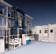
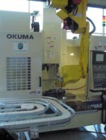
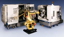
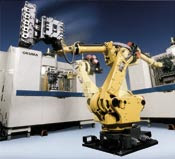
n a mixed process cell, turning and machining operations are performed with no work in process inventory accumulation. Shown here is a wheel-making cell with the turning operations performed at the turning center and the drilling of lug nut holes and the valve stem 
Automation can take the form of material and fixture storage capacity integrated into the machine load/unload capability. Random access for various parts is available for short run or 

CNC MACHINING::IS IT TIME TO AUTOMATE?

Machine shops seeking a more cost-effective method of CNC-machining should look to automation as a potential solution - and timing is everything.

Professionals in the automated CNC machining field suggest that automation can improve quality of machined parts, decrease setup time, stop fluctuations in production rates and raise the average percentage of functional machine tools in a shop from 65 percent to more than 85 percent.

However, before making the move to automation there are a few things to consider. First, the machining process selected for automation should be a reliable one from the onset in order to ensure the quality of automatically machined parts. Second, in order to ensure that the switch to automation will be cost effective, the price of automating each spindle should be less than $50,000 or about 50 percent of the cost of a spindle.

As the technology becomes more affordable, robotic vision seems to be the next frontier for CNC automation. One day soon, perhaps, machines equipped with vision technology will be able to guide themselves rather than having to rely on a fixture that holds a part to be machined in a specific orientation so that robots know where to pick it up. This will make it possible for operators to place an object on a conveyor within an accuracy of one inch and the robotic arm will seek, acquire and grip the part for loading.

CNC M-CODES

BELOW U CAN FIND ALL TYPES OF M-CODES THAT ARE USED IN CNC MACHINE PROGRAMMING.

 M codes chart
M00Program Stop
M01Optional (Planned) Stop
M02End of program
M03Spindle CW
M04Spindle CCW
M05Spindle OFF
M06Tool change
M07Coolant #2 ON
M08Coolant #1 ON
M09Coolant OFF
M10Clamp
M11Unclamp
M12Unassigned
M13Spindle CW & Coolant ON
M14Spindle CCW & Coolant ON
M15Motion +
M16Motion -
M17Unassigned
M18Unassigned
M19Oriented spindle stop
M20-M29Permanently unassigned
M30End of tape
M31Interlock bypass
M32-M35Unassigned
M36-M39Permanently unassigned
M40-M45Gear changes if used, otherwise unassigned
M46-M47Unassigned
M48Cancel M49
M49Bypass override
M50-M89Unassigned
M90-M99Reserved for user

CNC G CODES

CNC Machine Language
G-Code List

G-Code is one of a number of computer code languages that are used to instruct CNC machining devices what motions they need to perform such as work coordinates, canned cycles, and multiple repetitive cycles. Industry has standardized on G-Code as its basic set of CNC machine codes.

G-Code is the most popular programming language used for programming CNC machinery. Some G words alter the state of the machine so that it changes from cutting straight lines to cutting arcs. Other G words cause the interpretation of numbers as millimeters rather than inches. Some G words set or remove tool length or diameter offsets.

Below is a complete listing of current codes.

G-Code

Description

G00

Rapid Linear Interpolation

G01

Linear Interpolation

G02

Clockwise Circular Interpolation

G03

Counter Clockwise Circular Interpolation

G04

Dwell

G05

High Speed Machining Mode

G10

Offset Input By Program

G12

Clockwise Circle With Entrance And Exit Arcs

G13

Counter Clockwise Circle With Entrance And Exit Arcs

G17

X-Y Plane Selection

G18

Z-X Plane Selection

G19

Y-Z Plane Selection

G28

Return To Reference Point

G34

Special Fixed Cycle (Bolt Hole Circle)

G35

Special Fixed Cycle (Line At Angle)

G36

Special Fixed Cycle (Arc)

G37

Special Fixed Cycle (Grid)

G40

Tool Radius Compensation Cancel

G41

Tool Radius Compensation Left

G42

Tool Radius Compensation Right

G43

Tool Length Compensation

G44

Tool Length Compensation Cancel

G45

Tool Offset Increase

G46

Tool Offset Decrease

G50.1

Programmed Mirror Image Cancel

G51.1

Programmed Mirror Image On

G52

Local Coordinate Setting

G54 - G59

Work Coordinate Registers 1 Thru 6

G60

Unidirectional Positioning

G61

Exact Stop Check Mode

G65

Macro Call (Non Modal)

G66

Macro Call (Modal)

G68

Programmed Coordinate Rotation

G69

Coordinate Rotation Cancel

G73

Fixed Cycle (Step)

G74

Fixed Cycle (Reverse Tapping)

G76

Fixed Cycle (Fine Boring)

G80

Fixed Cycle Cancel

G81

Fixed Cycle (Drilling / Spot Drilling)

G82

Fixed Cycle (Drilling / Counter Boring)

G83

Fixed Cycle (Deep Hole Drilling)

G84

Fixed Cycle (Tapping)

G85

Fixed Cycle (Boring)

G86

Fixed Cycle (Boring)

G87

Fixed Cycle (Back Boring)

G88

Fixed Cycle (Boring)

G89

Fixed Cycle (Boring)

G90

Absolute Value Command

G91

Incremental Value Command

G92

Work Offset Set

G101

User macro 1 (substitution) =

G102

User macro 1 (addition) +

G103

User macro 1 (subtraction) -

G104

User macro 1 (multiplication) *

G105

User macro 1 (division) /

G106

User macro 1 (square root)

G107

User macro 1 (sine) sin

G108

User macro 1 (cosine) cos

G109

User macro 1 (arc tangent) tan

G110

User macro (square root)

G200

User macro 1 (unconditional branch)

G201

User macro 1 (zero condition branch)

G202

User macro (negative condition branch)


adsense

search engine

Custom Search